
Peltier modules or thermoelectric coolers (TEC) are basically thermoelectric heat pumps. It means that by supplying electrical energy, heat can be transported against its natural gradient, from one side of the peltier module where heat is absorbed to the other side, where heat is released. Thus, it is possible to use these peltier modules for heating or cooling applications. This behaviour is defined by the direction of the current. Theoretically, the temperature difference can go up to 73K for a simple element and up to over 100K for multi-level elements.
In general, peltier modules are used wherever cooling with a small temperature difference, precise control and dynamic behaviour is necessary. The application of Peltier modules are very diverse, starting from complex analysis technology in the field of medicine to light-sensitive CCD sensors and mobile cooling applications.
Working & physical effects
The name as well as the functionality of Peltier modules came from the so-called Peltier effect which is part of thermoelectricity. These include various physical effects in which thermal and electrical phenomena influence each other.
The four main effects related to thermoelectricity are:
1 . Peltier effect: When current flows through an arrangement of different conductor materials, the electrons moving through the conductor, has different energy levels in different conductor materials. If the electron hits an interface between two conductors, energy must either be absorbed or emitted to maintain the current flow. Energy absorption removes heat from the interface. Similarly release of energy heats the interface. The Peltier effect is responsible for the heat transport in an active Peltier element.
2. Seebeck effect: The cause of this thermoelectric effect lies in the bonding and the free flow of electrons in the metal. If a metal wire is only heated at one end, the vibrations of the lattice and the movement of the free electrons increase. Due to this, they expand and diffuse more and more towards the cold end where the kinetic energy of the electrons is low, as a result, they are not repelled by strong collisions. This means that there is an uneven distribution of charge in the wire. The heated side therefore has a shortage of electrons and the cold side has excess electrons. The resulting electrical voltage is also known as the thermoelectric voltage or Seebeck voltage. The magnitude of this voltage is determined by the Seebeck coefficient.
The attempt to tap this voltage fails because it influences the physical state in such a way that the voltages cancel each other out. However, to make this voltage usable, two different materials are used that generate voltages as different as possible. This difference can now actually be tapped and used to generate electricity. In addition, this material change can be repeated as often as required, so that considerable voltage can be achieve. The Seebeck effect reduces the Peltier effect, since a counter-voltage is built up here, which increases the internal resistance.
3. Thomson effect: If there is a temperature difference between two points on a current-carrying conductor, heat transport is increased or decreased depending on the type of metal. Although this is also transmitted through the thermal conductivity of the material, the resulting resistance ensures further heating. This means that the effect can only be demonstrated to a limited extent. The Thomson effect can be neglected for calculating the cooling capacity of Peltier modules.
4. Joule heating: Joule heat describes the heating of a current-carrying conductor due to its internal resistance. Basically, all electrical heating elements and light bulbs are based on this principle.
Joule heat is undesirable in cooling mode. As it adds heat to the side from which heat was extracted through the Peltier effect. As a result, the Joule heating is largely responsible for the fact that the total effect can only be increased up to the value Imax. Above this current, more heat is introduced than dissipated.
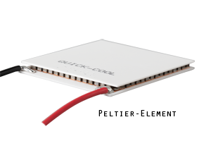
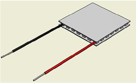
Structure: Peltier modules usually consists of two square plates, made of aluminium oxide ceramic, which are placed on top of one another at a distance of 3-5 millimeters. These plates are used to hold the complex structure together mechanically. On the one hand, the material must be thermally conductive in order to allow the heat flow and, on the other hand, it must be electrically insulated so that the series connection of the material pairings is not short-circuited. There are small cuboids in between them, called legs or dices, made of a semiconductor material such as bismuth telluride or silicon germanium. The p- and n-doping of the material results in two different conductor materials which, when energized, produce the effects described above.
In a Peltier module, all the electrical conductors made of two different materials are electrically connected in series, so that heat is repeatedly absorbed and emitted. The spatial arrangement of the individual conductors is now selected in such a way that the energy-absorbing interfaces are exclusively on one side of the Peltier, the energy-emitting interfaces on the other side. So, the current meanders back and forth between the two ceramic plates. Consequently, from an electrical point of view, the arrangement is a series circuit; from a thermal point of view, the conductors are all parallel.
The thermal and electrical properties of a Peltier module are defined by the number of dices and their geometry.
As already described, the various effects superimpose and thus influence the desired heat transport of the Peltier module. Above a current Imax or voltage Umax, the undesirable effects predominate and a further increase in the energy input causes a decrease in the transport capacity. With bismuth telluride, this effect is achieved at around 0.12 V per pair of dice and 25 degrees Celsius warm side temperature.
The cooling capacity on the cold side is calculated as follows:
Q = S x I x TC - R x I2 - Gth x ∆T
Peltier effect
Joule warmth
natural heat flow from warm to cold
As mentioned in the description of each effects, the resistance R is influenced by the Seebeck effect. In addition, all material properties are temperature dependent. The temperature of a semiconductor dice describes a curve over the spatial expansion and even exceeds the temperature of the warm side inside.
A correct mathematical description is therefore extremely complex.
A module with 127 pairs of dices has an Umax of approximately 15V, whereas a module with 241 pairs of dices has approximately 28V. The vast majority of peltier modules are based on the same grid with 17, 31, 63, 71, 127, 61, 241 pairs of dices across all manufacturers. There are more or less pairs, depending on how the pairs of legs are arranged between the ceramics and how the electrical connection is made. For peltier modules with the same number of dices, the power is set via the maximum current. The thinner the modules, the more powerful they become. Thinner dices reduce internal resistance, Joule heating and thermal resistance, while the cooling capacity increases.
Design:
There are different designs of Peltier modules. The most common form is a small square plate with electrical connections through which a direct current can be fed. By changing the current strength and direction, the temperature of contacting objects can be controlled. This is the most common design.
Since high-power modules are thinner than low-power modules, it is often impossible to insert a cable into the space here. In this case, the ceramic side to which the electrical connection is attached is chosen to be somewhat larger and the connections are made on the resulting protrusion. This protrusion is called a porch. The porch also allows integration without wires, for example with push pins or terminals, since the exposed electrical connections may be directly tapped. With thin modules it is also common that the hot side is larger on two sides than the cold side ceramic.
In this case, the plus (+) pole is connected on one side and the minus (-) pole on the other side.
The technical setup for cooling an object using peltier technology usually consists of a peltier element, a heat sink and the object of interest. If these components are appropriately selected and mounted, the object temperature can be controlled between minus 40 °C and plus 200° C.
The difficulty of this technique lies in the dimensioning. After all, the peltier element generate a temperature difference instead of a defined temperature. This temperature difference depends on the power supplied, which drives the peltier effect, and the thermal power to be transported. In addition, there are the temperatures in the material, which influence all electrical and thermal effects. The temperature of the object to be cooled is then a function of this temperature difference and the temperature on the warm side. The warm side temperature is determined from the heat sink attached to it.
The engineers at Quick-Ohm can configure the components to achieve the desired requirements. If necessary, a design can be made on the basis of which a product can be brought to series production.
51 important rules for Peltier modules:
1. Peltier modules are usually rectangular plates with edge lengths between 10 mm and 50 mm. The thickness is in the range between 3 mm and 5 mm. Two cables for the electrical supply protrude from one of the narrow sides.
2. Peltier modules from Quick-Ohm become cold at the top if the element is positioned so that the red wire is on the right and is positively energized here. (red-right-above-cold)
3. The temperature difference by peltier effect arise when electrical energy flow across two different conductors connected to an interface.
4. The Peltier module combines the arrangement of many interfaces made of two different conductor materials, which in their sum, driven by electrical energy, transport heat from one side ("cold side") to the other side ("warm side") of the element.
5. The transport of heat causes a temperature drop where heat is removed and a temperature rise in the heat absorption zone.
6. The Peltier element generates a temperature difference between its two contact surfaces by supplying electrical energy.
7. Without any further thermal connection to a heat sink, the electrical energy supplied remains in a Peltier element and leads to an uncontrolled increase in temperature.
8. A Peltier module must be given the possibility to release the energy supplied.
9. If a Peltier module is connected to a power source without establishing a thermal connection, it will overheat within a very short time.
10. If a Peltier module is connected to an insufficient heat sink, the desired temperature control effect cannot be controlled.
11. The most common deficiency in the construction of Peltier applications is the inadequate dimensioning of the heat sink.
12. The temperature difference at the Peltier element depends on the power supplied, the power transported and the temperature level at which the process takes place.
13. The relationship between the electricity supplied and the heat transported (cooling capacity Q of the Peltier module) roughly follows a polynomial function of the second degree. The heat transport increases with increasing electricity up to a maximum value. Beyond this value, the transport performance decreases. The module is overloaded here.
14. If the supplied current is roughly twice the value Imax (data sheet), no more heat is transported. From this point in time, energy is supplied to both sides of the Peltier element. The element acts as a pure heater.
15. The relationship between the supplied current and the temperature difference roughly follows a polynomial function of the second degree. The temperature difference between the two sides of the Peltier module increases with increasing current up to a maximum value. The maximum temperature difference drops beyond this value Imax. The module is overloaded here.
16. If the supplied current exceeds twice the value Imax (data sheet), the sign of the temperature difference changes. The surface temperature of both sides increases as a result of a further increase in current.
17. The power supplied by a Peltier module increases disproportionately compared to the cooling power. As a result, it can be advantageous to replace a single fully activated high power element with several low power elements. This measure reduces the energy consumption and the demands on the downstream heat sink.
18. If a qualitatively adequate cooling design has been created, this creates an area of low temperature. We perceive this zone as "cold".
19. If the cooling zone is supplied with energy, its temperature rises. Energy is supplied, for example, through the penetration of ambient heat or through active parts in the cooling area.
20. If the energy Qmax is supplied to the cooling zone and the supplied current is I = Imax, if the temperature on the “warm side” is 25 ° C, the heat transport comes to a standstill. The Peltier module is no longer able to achieve a cooling effect. These values are defined as the nominal data of the Peltier module and can be read from the data sheet.
21. In order to transport an amount of heat Q ([Q] = watt) and at the same time to achieve a “cooling effect, the nominal power Qmax of the Peltier element must be greater than this amount of heat.
22. The direction of heat transport is controlled by the direction of the current and can take place in both directions.
23. The current direction controls whether the Peltier module cools or heats.
24. The current amplitude controls how strongly the Peltier module cools or heats.
25. An object to be cooled must be thermally contacted with the cold side of the Peltier module. This connection represents a thermal resistance. The heat flow through this thermal resistance creates a temperature gradient. The object never reaches the temperature of the Peltier cold side.
26. The energy that accumulates on the warm side of the Peltier module must be transferred to a cooling medium (air, water, etc.) via a heat exchanger. This heat exchanger is described qualitatively via its thermal resistance Rth. The cooling power Q and the supplied power Pzu flow through this resistance and generate a temperature drop. The temperature on the warm side of the Peltier module exceeds the temperature of the cooling medium by this temperature drop.
27. The rule of thumb for designing the heat exchanger for Peltier modules is: Rth <10K / Pzu
Where:
- Rth = thermal resistance of the heat sink
- Q = dissipated heat
- Pzu = supplied electrical power
28. According to the manufacturer, the thermal resistance of a heat sink usually refers to a homogeneous heat application over the entire heat absorption surface of this heat sink. When cooling a Peltier module, the effective thermal resistance compared to this specification is significantly worse (worse = larger) due to the small contact area with the Peltier module.
29. If an object is to be cooled down by 30 Kelvin compared to its surroundings, the Peltier module must generate a temperature difference of around 50 Kelvin between its surfaces in order to enable the heat flow from "cold" to "warm".
30. In order to be able to generate a very low temperature with Peltier modules, several Peltier modules may have to be thermally connected in series. (on top of each other)
31. If two Peltier modules are thermally connected in series for cooling mode, the pre-cooling stage must transport the sum of the heat output and the electrical power supplied to operate the first stage. The second stage must therefore be more powerful than the previous one.
32. So that the second stage of a two-stage Peltier module can dissipate the waste heat from the first stage, the contact surfaces must be completely connected to one another.
33. The size of the individual surfaces of a multi-level Peltier module must be the same in order to produce a thermally coherent connection between the levels.
34. Peltier modules with more than two stages cause significant differences in nominal power between the first and the last stage. Such different levels can no longer be accommodated on the same area.
35. Multi-stage Peltier modules have to be built up from differently sized levels due to the manufacturing process. This causes the thermal interconnection to lose quality. Large parts of it become ineffective. Consequently, the individual levels are effectively equally strong. A real cascading does not take place. Most of the electrical power used dissipates in the functionless protruding edges.
36. In order to thermally interconnect a large number of Peltier stages, homogenizing intermediate layers made of thermally conductive material must be introduced.
37. The cooling efficiency of Peltier elements decreases at low temperatures and increases at high temperatures.
38. The Peltier effect disappears at temperatures below minus 150 °C.
39. It is not possible to use Peltier modules to reach temperatures below minus 150 °C.
40. The increasing pre-cooling of the “warm side” of a Peltier module continues to an increasingly lesser extent on the “cold side”.
41. Every Peltier module is a thermal generator.
42. The maximum efficiency of the conversion of thermal power into electrical power reaches a maximum of 5% with Peltier modules.
43. Since the construction of a thermal generator, including its thermal connection to the source and sink, requires a certain amount of effort, and because the conversion efficiency is quite low, the value of the energy generated does not meet cost.
44. For the generation of electrical energy with Peltier modules, thermal energy must be conducted from a “warm zone” through the Peltier module into a “cold zone”. Through this tapping of energy, the temperature of the warm zone sinks and the temperature of the cold zone rises.
45. A thermal excess heat can never be fully used for thermoelectric conversion.
46. Peltier modules may only be subjected to pressure on the ceramic plates. Forces of up to 200 Newtons per square centimeter can act on upon it. A shear load or tension is not allowed.
47. Peltier modules are to be protected from vibrations.
48. Due to the load restrictions, Peltier assembly should not be done only using adhesives.
49. For long term assemblies, the Peltier module will always be clamped between the heat sink and the cooling zone.
50. In order to minimize thermal stresses, a connection between the "heat sink" and the "temperature control area" must be resilient. (e.g .: disc springs instead of washers - see error! Reference source could not be found.)
51. If the construction requires that the assembly to be carried out exclusively by means of adhesives, it must be ensured that no shear or tensile forces act on the Peltier module.